How to Replace a Windshield Wiper Motor and Transmission Linkage Assembly

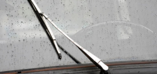
This set of repair instructions apply to 2005-2009 Pontiac G62008-2012 Chevy Malibu2007-2009 Saturn Aura Often referred to as a Wiper System Module, this is made up of a wiper motor and the mechanical linkage that actuates the wiper blades. After several years of use or from excessive conditions like snow, this linkage can break and cause the wiper blades to move sporadically or not at all. Ensure that the wipers are set to the ‘PARK’ position Open hood Remove wiper arm nut finish cap Remove the wiper arm nut To remove the wiper arm requires a special tool.** Removing the wiper arm...
Automotive Terminology, Codes, Abbreviations and Other Words That Can Be Just Plain Confusing

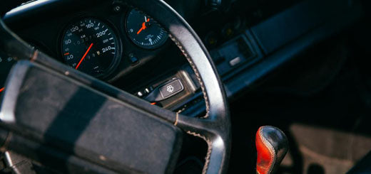
Most auto technicians and car parts people have a separate language which may not make any sense to the average person trying to work on their car. I am going to try to create a list of the most common terms and abbreviations to help you navigate through this world of car-speak. Some of these may seem self-explanatory but I don’t want to leave anything out that may be easily mistaken for something else. So, what does ___ mean? : 4×2 = Four by Two, Only two of the drive wheels are powered at any time during driving 4×4 =...
A Basic Description Of Automotive A/C Systems And How They Work

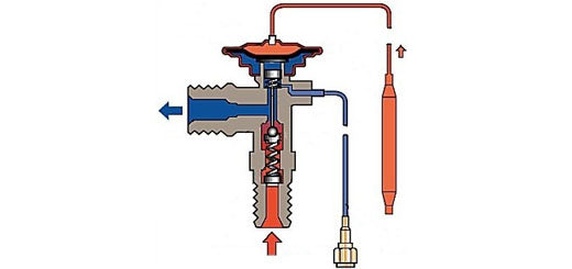
Automotive AC systems can be intimidating if you are to jump in headfirst without a little background on exactly what is happening inside the system. I am writing this article to give some insight into the workings of your car’s AC system, and hopefully allow you to properly diagnose and repair your own AC system. The first thing I need to talk about is the proper equipment used to service an air conditioning system. Most of the system can be serviced using common hand tools, but there are a few specialty tools needed for proper service of your AC system....
What are Hollander Part Numbers?!


People often ask why their new part has a “Hollander” part number on it. Is Hollander a brand? What exactly is a Hollander part?! Hollander is nothing more than a universal part numbering system. Hollander is a company which was originally created in the 1930’s to help the salvage yard industry organize their parts into a universal and interchangeable part numbering system. You can read their interesting company history here: Hollander Interchange Company History. Their numbering system has recently taken off for more than just the salvage industry. Many internet auto-parts companies, such as APDTY and brands like Dorman, are using this flexible system...
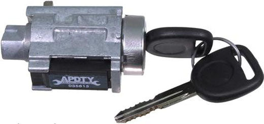
How To Replace GM Passlock Ignition Key Lock Cylinder and Relearn Procedure